Show Me The Weather

After connecting the e-ink display to the Pico and managing to get it to display in landscape mode I felt I’d solved the unknowns in making this e-ink weather display. Now it was time to decide what I was going to show, and how I was going to show it.

One Python example I’d found used a weather API called OpenWeather, so I went and signed up. Yet no matter what I seemed to do in terms of requesting API keys, and even waiting a day for activation, I was never able to make a valid request. In the meantime, with a little more Googling I found Meteo’s API. It turned out to be very easy to work with and had everything I’d need.

I chose some data fields I wanted to display and opened Photoshop to start a basic layout.
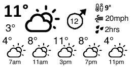
Design for an e-ink weather display showing maximum and minimum daily temperature, overall weather, wind gusts, and a summary for every 4 hours

I wanted minimum and maximum temperatures during the day, a nice summary icon, average wind speed, and then a bit more info about how it would feel which is where the 9 degrees (“feels like” temperature), 20mph (wind gusts), and 2hrs (duration of rainfall during the day) came from. Below that is a little summary of what the weather looks like at four hour intervals..

The API call is just a request to a URL, such as this:

https://api.open-meteo.com/v1/forecast?latitude=XXXXX&longitude=XXXXX&hourly=temperature_2m,windspeed_10m,winddirection_10m,windgusts_10m,weathercode&daily=temperature_2m_min,temperature_2m_max,sunrise,sunset,windspeed_10m_max,windgusts_10m_max,winddirection_10m_dominant,precipitation_hours,apparent_temperature_max,weathercode&timezone=GMT&windspeed_unit=mph

You can request more fields in either the hourly or daily summary, and the documentation was pretty clear too.

The return is JSON and easily parsed with Micropython. I wrote a small module to do it all:

import network, rp2, time
import urequests
import json
import sys
from io import BytesIO

LATITUDE = 'XXXXX'
LONGITUDE = 'XXXXX'

BASE_URL = 'https://api.open-meteo.com/v1/forecast?' 
URL = BASE_URL + 'latitude=' + LATITUDE + '&longitude=' + LONGITUDE + '&hourly=temperature_2m,weathercode&daily=temperature_2m_min,temperature_2m_max,sunrise,sunset,windspeed_10m_max,windgusts_10m_max,winddirection_10m_dominant,precipitation_hours,weathercode&timezone=GMT&windspeed_unit=mph'

# API documentation at https://open-meteo.com/en/docs
class Meteo:
    def __init__(self):
        self.json = None
        return
    
    def get_data(self):
        # Make GET request
        response = urequests.get(URL)
        if response.status_code != 200:
            print("Error")
            print(response.status_code)
            print(response.content);
            response.close();
            raise Exception("Error getting weather data " + response.status_code)
        else:
            self.json = response.json();
            response.close();
            return self.json;

I’d call it from a function, just so it was easier to test:

def getWeatherData():
    weather = meteo.Meteo();
    weather.get_data();
    return weather;

And accessing the data is just like accessing any Python object e.g. to get the maximum daily temperature:

max_daily = str(round(weather.json["daily"]["temperature_2m_max"][0]))

So far so simple, and I was quickly on to drawing all of this to the display, which is the subject of the next post.

Micropython E-ink Display Rotation

By default, sending pixels from a Raspberry Pico to a Waveshare e-ink display will result in a portrait image. In the case of the 2.13inch display I started with, this means a screen of 122 pixels wide by 250 pixels high.

But what if you want to display in portrait mode? As someone who’s used to the simple world of CSS it was actually fun to get back into the world of bits and pixels again.

Just like the ZX Spectrum, where I started programming, the display is stored as a list of bytes where each byte is eight consecutive pixels, either set to 1 to display a dark pixel or 0 for white (or clear).

In Micropython, this is stored as a byte array. So the code that sets up the display looks like this:

self.buffer_black = bytearray(self.height * self.width // 8)

Thankfully, there’s a helper module in the shape of Framebuffer which makes changing the value of these pixels much easier. It contains methods to write text, lines, rectangles and circles and, most usefully, to draw images at arbitrary coordinates using the blit command.

Not only does blit make it easier to draw, say, a 50×50 image onto the 122×250 display, but it also makes it much easier to draw an 8-bit image onto the 1-bit display. You start by setting a Framebuffer object with its data source as the byte array, such as:

self.imageblack = framebuf.FrameBuffer(self.buffer_black, self.width, self.height, framebuf.MONO_HLSB)

Where the first argument is the byte array, with and height are self explanatory, and framebuf.MONO_HLSB means that this framebuffer is a mono (1-bit) image, with horizontal bits stored as a byte.

To draw an image on top, assuming you have the pixel data in a variable called image_buffer, you can do something like:

self.imageblack.blit(framebuf.FrameBuffer(image_buffer, width, height, framebuf.GS8), x, y, key)

Where width and height are the width and height of the image, framebuf.GS8 signifies an 8-bit grayscale image, x and y are the coordinates to draw to, and key tells the blit method which pixels in the image it should treat as transparent. This allows you to draw just the black pixels onto the screen without the “white” pixels (or 0 bits) overwriting anything that’s already on the screen. Because the frame buffer takes the image_buffer bytearray as a parameter but changes the pixels in it by reference, any changes to self.imageblack (which is a Framebuffer object) are applied to the bytearay in self.buffer_black – which represents the actual pixel data.

So far so simple as far as drawing an image to the screen goes, assuming you’re still working in portrait mode. I made myself a helper function to load raw files from the on-board memory:

def drawImage(display_buffer, name, x, y, width, height, background=0xFF):
    image_data = get_image_data(name)
    if image_data:
        display_buffer.blit(image_data, x, y, background)
    else:
        image_buffer = bytearray(width * height)
        filename = 'pic/' + name + '.raw'
        with open (filename, "rb") as file:
            position = 0
            while position < (width * height):
                current_byte = file.read(1)
                # if eof
                if len(current_byte) == 0:
                    break
                # copy to buffer
                image_buffer[position] = ord(current_byte)
                position += 1
        file.close()
        display_buffer.blit(framebuf.FrameBuffer(image_buffer, width, height, framebuf.GS8), x, y, background)

Drawing a landscape image instead of portrait should be as simple as:

  1. Set up a Framebuffer with a width equal to the e-ink display height, and a width equal to the e-ink display width
  2. Draw to the Framebuffer
  3. Transpose columns of pixels into rows in a new bytearray
  4. Send to the e-ink display

It seemed like exactly the sort of thing that someone would already have tackled, and so it proved. So with some Googling and adjustment of width/height variables to suit the display I was working with I came to this:

def rotateDisplay(display):
    epaper_display = bytearray(epd.height * epd.width // 8)
    x=0; y=-1; n=0; R=0
    for i in range(0, epd.width//8):
        for j in range(0, epd.height):
            R = (n-x)+(n-y)*((epd.width//8)-1)
            pixel = display[n]
            epaper_display[R] = pixel
            n +=1
        x = n+i+1
        y = n-1
    epaper_buffer = framebuf.FrameBuffer(epaper_display, epd.width, epd.height, framebuf.MONO_HLSB)
    return epaper_display;

And I have to confess I didn’t worry too much about the details. Not until I ran it and the output was complete garbage.

It took a while to work out what I was doing wrong, but once I found the problem the solution made complete sense: I was inputting a Framebuffer stored as MONO_HLSB but the function above transposed the position of bytes, not individual bits. In other words, chunks of 8 pixels were being moved to the right place on the screen, but forming a column rather than a row. No wonder it looked bad.

The solution was simple: start with a Framebuffer of the type MONO_VLSB, where the bytes represent a column of 8 pixels, not a row. Then the transposition naturally mapped to MONO_HLSB.

I ended up with something like this:

display = bytearray(epd.height * epd.width // 8)
    display_buffer = Screen(display, epd.height, epd.width, framebuf.MONO_VLSB)
    display_buffer.fill(0xff)
    --- 
      Draw somethings here
    ---
    epaper_display = rotateDisplay(display)

where Screen was an extension of the Framebuffer class, necessary because the width and height parameters weren’t accessible in a native Framebuffer object. It just felt nicer to store them “in place” rather than pass another parameter around.

class Screen(framebuf.FrameBuffer):
    def __init__(self, display, width, height, encoding):
        self.display = display
        self.width = width
        self.height = height
        self.encoding = encoding
        return

The final wrinkles was that the e-ink display was 122 pixels “wide” (or now 122 pixels high, as I was trying to work in landscape mode), and therefore not a number that formed a whole number of bytes. Because of the way I was treating the screen, it meant my top left origin was at the coordinates (0, 6), which felt a bit nasty but was something I could live with. The alternative would have been to transpose the whole thing down 6 pixels using another Framebuffer, but frankly I couldn’t be bothered.

Writing To The E-ink Display With Micropython

I’d gotten as far as running a few lines of code on the Pico, so the next thing was to work out if I could display anything at all on the e-ink display. Since I’d already messed up by buying the wrong HAT type, I still had a small doubt about whether I would get the two to work together at all.

Waveshare has its own Github respository so I headed there to track down the correct Python file. I knew I needed one of the files that started with “Pico_ePaper-2.13-“, but which one?

There was a little stick on the display telling me I had a “v3”, but working out whether I had an A, B, C or D model was a mixture of guesswork and deduction. The file for both B and C appeared to support multiple colours, which is not what I had, so it wasn’t those. I had nothing else to go on, so I tried both A and D. Neither seemed to work properly, although I did get the screen to flicker a bit so something was happening.

I can’t even remember how I finally got the thing working, but it appears to be through a hybrid of files that started as Pico_ePaper-2.13-B_V4.py with all the code that referred to the red image data removed. The whole process was made more difficult by the fact that I seemed to have messed up connecting two of the pins, having not spotted that there was a pin labelled “GND” right between “GP21” and “GP22” on the Pico board.

This was my “driver” module:


from machine import Pin, SPI
import framebuf
import utime

EPD_WIDTH       = 122
EPD_HEIGHT      = 250

RST_PIN         = 12
DC_PIN          = 8
CS_PIN          = 9
BUSY_PIN        = 13

class EPD:
    def __init__(self):
        self.reset_pin = Pin(RST_PIN, Pin.OUT)
        
        self.busy_pin = Pin(BUSY_PIN, Pin.IN, Pin.PULL_UP)
        self.cs_pin = Pin(CS_PIN, Pin.OUT)
        if EPD_WIDTH % 8 == 0:
            self.width = EPD_WIDTH
        else :
            self.width = (EPD_WIDTH // 8) * 8 + 8
        self.height = EPD_HEIGHT
        
        self.spi = SPI(1)
        self.spi.init(baudrate=4000_000)
        self.dc_pin = Pin(DC_PIN, Pin.OUT)
        
        
        self.buffer_black = bytearray(self.height * self.width // 8)
        self.init()

    def digital_write(self, pin, value):
        pin.value(value)

    def digital_read(self, pin):
        return pin.value()

    def delay_ms(self, delaytime):
        utime.sleep(delaytime / 1000.0)

    def spi_writebyte(self, data):
        self.spi.write(bytearray(data))

    def module_exit(self):
        self.digital_write(self.reset_pin, 0)

    # Hardware reset
    def reset(self):
        self.digital_write(self.reset_pin, 1)
        self.delay_ms(50)
        self.digital_write(self.reset_pin, 0)
        self.delay_ms(2)
        self.digital_write(self.reset_pin, 1)
        self.delay_ms(50)


    def send_command(self, command):
        self.digital_write(self.dc_pin, 0)
        self.digital_write(self.cs_pin, 0)
        self.spi_writebyte([command])
        self.digital_write(self.cs_pin, 1)

    def send_data(self, data):
        self.digital_write(self.dc_pin, 1)
        self.digital_write(self.cs_pin, 0)
        self.spi_writebyte([data])
        self.digital_write(self.cs_pin, 1)
        
    def ReadBusy(self):
        print('busy')
        while(self.digital_read(self.busy_pin) == 1): 
            self.delay_ms(10) 
        print('busy release')
        self.delay_ms(20)
        
    def TurnOnDisplay(self):
        self.send_command(0x20)  # Activate Display Update Sequence
        self.ReadBusy()
        
    def TurnOnDisplayPart(self):
        self.send_command(0x20)        
        self.ReadBusy()

    def SetWindows(self, Xstart, Ystart, Xend, Yend):
        self.send_command(0x44) # SET_RAM_X_ADDRESS_START_END_POSITION
        self.send_data((Xstart>>3) & 0xFF)
        self.send_data((Xend>>3) & 0xFF)

        self.send_command(0x45) # SET_RAM_Y_ADDRESS_START_END_POSITION
        self.send_data(Ystart & 0xFF)
        self.send_data((Ystart >> 8) & 0xFF)
        self.send_data(Yend & 0xFF)
        self.send_data((Yend >> 8) & 0xFF)
        
    def SetCursor(self, Xstart, Ystart):
        self.send_command(0x4E) # SET_RAM_X_ADDRESS_COUNTER
        self.send_data(Xstart & 0xFF)

        self.send_command(0x4F) # SET_RAM_Y_ADDRESS_COUNTER
        self.send_data(Ystart & 0xFF)
        self.send_data((Ystart >> 8) & 0xFF)
    

    def init(self):
        print('init')
        self.reset()
        
        self.ReadBusy()   
        self.send_command(0x12)  #SWRESET
        self.ReadBusy()   

        self.send_command(0x01) #Driver output control      
        self.send_data(0xf9)
        self.send_data(0x00)
        self.send_data(0x00)

        self.send_command(0x11) #data entry mode       
        self.send_data(0x03)

        self.SetWindows(0, 0, self.width-1, self.height-1)
        self.SetCursor(0, 0)

        self.send_command(0x3C) #BorderWavefrom
        self.send_data(0x05)

        self.send_command(0x18) #Read built-in temperature sensor
        self.send_data(0x80)

        self.send_command(0x21) #  Display update control
        self.send_data(0x80)
        self.send_data(0x80)

        self.ReadBusy()
        
        return 0       
        
    def display(self):
        self.send_command(0x24)
        for j in range(0, self.height):
            for i in range(0, int(self.width / 8)):
                self.send_data(self.buffer_black[i + j * int(self.width / 8)])   
        self.TurnOnDisplay()

    
    def Clear(self, colorblack):
        self.send_command(0x24)
        for j in range(0, self.height):
            for i in range(0, int(self.width / 8)):
                self.send_data(colorblack)
        self.TurnOnDisplay()

    def sleep(self):
        self.send_command(0x10) 
        self.send_data(0x01)
        
        self.delay_ms(2000)
        self.module_exit()
        

I haven’t yet managed to track down what all the send_command statements actually do, but I feel sure there must be some documentation for them somewhere.

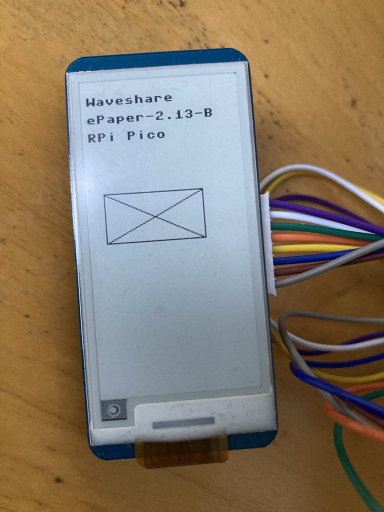
Anyway, finally, I had the equivalent of “hello world” on the display, without really knowing how. Also, I had discovered that the epaper display naturally preferred to display in portrait mode, which wouldn’t work for the layout I had in mind for my weather display.

    epd = EPD()
    epd.Clear(0xff)
    epd.imageblack = framebuf.FrameBuffer(epd.buffer_black, epd.width, epd.height, framebuf.MONO_HLSB)
    
    epd.imageblack.fill(0xff)
    #epd.imagered.fill(0xff)
    epd.imageblack.text("Waveshare", 0, 10, 0x00)
    epd.imageblack.text("ePaper-2.13-B", 0, 25, 0x00)
    epd.imageblack.text("RPi Pico", 0, 40, 0x00)
    #epd.imagered.text("Hello World", 0, 55, 0x00)
    epd.display()
    epd.delay_ms(2000)
    
    epd.imageblack.vline(10, 90, 40, 0x00)
    epd.imageblack.vline(90, 90, 40, 0x00)
    epd.imageblack.hline(10, 90, 80, 0x00)
    epd.imageblack.hline(10, 130, 80, 0x00)
    epd.imageblack.line(10, 90, 90, 130, 0x00)
    epd.imageblack.line(90, 90, 10, 130, 0x00)
    epd.display()
    epd.delay_ms(2000)

It felt like I’d conquered most of the unknowns anyway, so now onto showing some actual weather.

Getting Started With The Raspberry Pi Pico

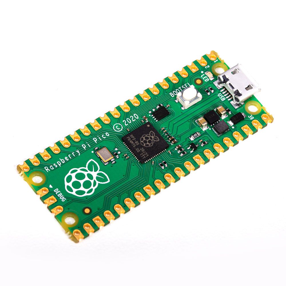
Raspberry Pi Pico

The whole Raspberry Pi craze has passed me by before. Mainly because I have no competency whatsoever in electronics, and when it comes to using it just as a small computer I’ve had no need for one.

I don’t really know what drew me to the Raspberry Pi Pico, but it just looked like such a fun little thing to experiment with. I think it’s partly that it’s not just a small computer, because there’s no keyboard or mouse input, no monitor, and the only way to program it (that I know of so far) is through an attached computer. And with a very low power consumption it comes across more as a component to be used in something else than a mini-computer. Plus it can be programmed in Micropython, which is more-or-less a subset of the Python language with which I’m familiar (although no expert, but it looks pretty much the same as every other language to be honest).

But given my previously mentioned lack of electronics competency that alone wouldn’t be enough to lure me in, but the more I started to look at it the more it appeared that competency in electronics really wasn’t al that important. So many components, whether e-ink or LCD displays, cameras or motion sensors seem to be almost plug-and-play. Even I couldn’t mess that up.

Finally, I’d recently installed Hive Smart Radiators, and although the app is okay for controlling them, I’d been thinking how nice it would be to have small, unobtrusive controls for them in key rooms so it’s harder to forget to turn heating off in rooms that aren’t going to be used for most of the day, or turning them back on again if someone comes home early. I’d looked at cheap Android tablets that I could then build an app for, but for a kind of “at a glance” display I’d either have to have the screens always on, or look at something more expensive like OLED. Android, or cheap old model Apple tablets, just seemed like overkill, but also lacking in flexibility.

So a Pico looked fun and an avenue to explore, but where to start?

Starting Small: An E-ink Weather Display

The thing that piqued my interest was tiny e-ink displays, like the ones from Waveshare. I knew they’d be low power and ideal for infrequently updated displays, and although maybe not quite what I wanted for smart radiator controls (but then maybe they will be), I couldn’t get the idea of building something with one out of my head.

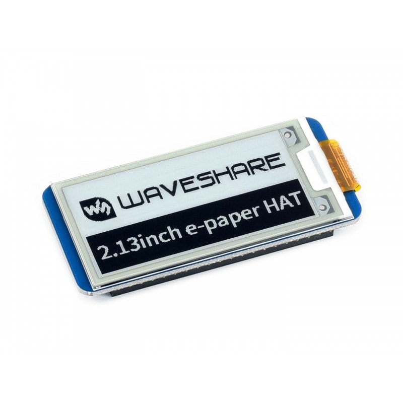
Waveshare 2.13 inch e-ink display

I decided I’d start with something smaller than a heating controller and settled on a weather display. My partner is always asking me if she’s going to need an umbrella that day, despite having a smartphone sitting in front of her, so I could kid myself it would be useful to install by the front door. Plus, some of the first search results I’d pulled up when looking at how hard it might be to program an e-ink were weather displays. (Albeit for a Raspberry Pi, not the Pico, and with a larger screen than I was planning. But it was some working code to give me direction.)

I had my project, and it looked achievable, so I just needed to buy some kit and start playing.

Buying The Right Equipment

In trying to buy just a Pico and an e-ink display my lack of knowledge almost set me back. Just in time, I realised that I needed a Pico W, which is a Pico with an onboard wifi controller, otherwise my weather display wouldn’t be able to retrieve weather information. (Although it’s possible to add an external controller, it’s much easier just to have it there at the start.)

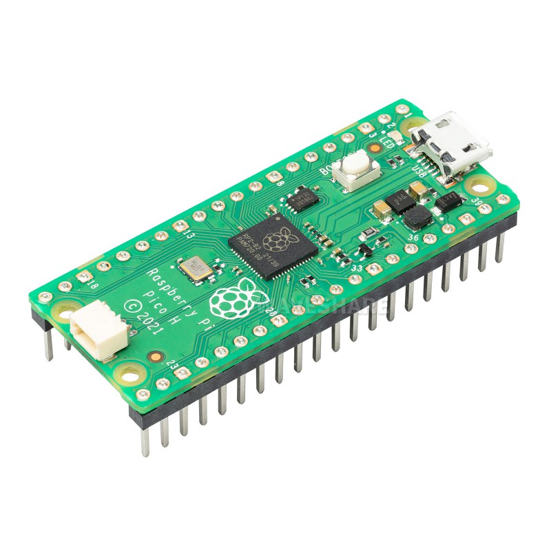
Secondly, I needed a Pico with soldered headers to make the connection to the display much easier. In fact, as I don’t (yet) own a soldering iron, it was the only way to make the connection possible. The Pico with soldered headers costs a few pounds more, but easily worth the extra convenience. As shown in the image below, the headers are the “spikes” that make it easy to attach cables or other devices.

Raspberry Pi Pico with soldered headers

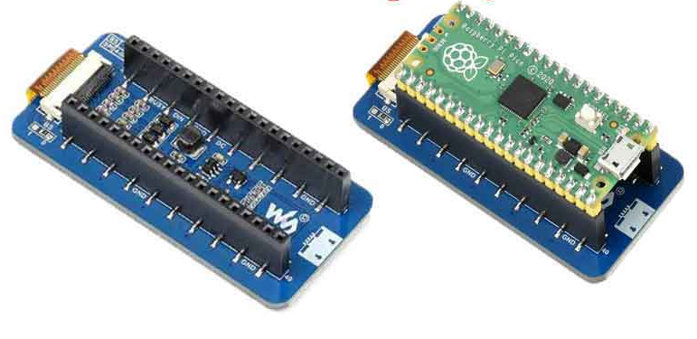
I knew then that if I bought an e-ink display with a HAT connection (which apparently stands for “hardware attached on top” and is easy to remember because it really does look lik you’re putting a hat on it) all I’d have to do is drop it on top.

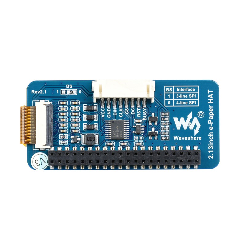
The first confusion came when I tried to attach the two. The Pico had two rows of pins, but the display only had a single connection row. It had me stumped for a while, but then I worked out that I’d bought the wrong type of HAT. Apparently the e-ink display I’d bought hat a HAT configuration for a standard Raspberry Pi, not for a Pico.

This is what not to buy for a Pico:

Waveshare e-ink display with Raspberry Pi HAT connection

Whereas what I wanted would attach like this:

Waveshare e-ink display attached via HAT to Raspberry Pi PIco

It wasn’t a disaster, though as it also came with a cable connection. It just came down to working out how on earth to join the two things together.

A cable for a Waveshare e-ink display

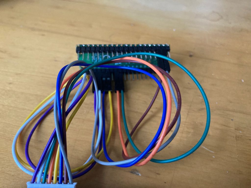
Googling for the connections wasn’t too hard, as it’s all on the Waveshare site, but connecting them was made harder than it should be due to failing close-up eyesight which meant that matching microscopic pin numbers on the Pico to coloured cables from the display wasn’t as easy as it could have been.

Cable connections from a Raspberry Pi Pico to Waveshare e-ink display

Installing the Micropython firmware and connecting to the Pico with the Thonny IDE was straightforward and I was able to run an example piece of code to turn the onboard LED on and off within a few minutes. But I had a feeling that getting the e-ink display to show anything was going to be a little harder. For various reasons, so it proved, but that’s going to be covered in the next post.

Accessing Cordova Config Info From JavaScript Without Plugins

I wanted to access the current build number for analytics, but there seemed to be no easy way to get at the info that Cordova puts into the plist file (Xcode) and AndroidManifest.xml (Android Studio).

My solution is to copy those to files into the www folder at build time and then load them with AJAX. It means adding the following line in the iOS project in ios/cordova/lib/copy-www-build-step.js, somewhere near the end:

shell.cp('-f', path.join(path.dirname(PROJECT_FILE_PATH), path.basename(PROJECT_FILE_PATH, '.xcodeproj'), '*.plist'), dstWwwDir);

As part of the build process, this copies the plist file into the root web directory as it’s deployed onto the device (meaning there are no changes to the source filesystem). So if it doesn’t seem to work, write some kind of check to see if the file actually gets copied.

Then in Android Studio, inside build.gradle for the app module, right before the line that starts android {:

task copyFiles(type: Copy) {
description = 'copying some file(s)....'
from "../app/AndroidManifest.xml"
into '../app/src/main/assets/www/'
}
preBuild.dependsOn copyFiles

Unlike the Xcode version, this copies AndroidManifest.xml into the www root directory before it’s deployed to the device, so the file will appear inside the www directory. It’s overwritten each time in case there are any changes.

Then inside JavaScript, to access data within those files I used jQuery to parse AndroidManifest.xml and a library called Plist Parser to make iOS just as easy. Plist Parser turns the annoyingly structured file into a JSON object that’s trivial to navigate through.

The JavaScript code, assuming there’s a check for platform somewhere else, is below. I mainly wanted CFBundleVersion (iOS) and android:versionCode (Android), but you can access anything else in the file too:

if (platform == 'android') {
$.ajax({
url: 'AndroidManifest.xml',
dataType: 'text',
success: function (response) {
var xml = $(jQuery.parseXML(response));
var root = xml.find('manifest');
if (root) {
if (root.attr('android:versionCode')) {
var app_version = root.attr('android:versionCode');
}
if (root.attr('package')) {
var app_id = root.attr('package');
}
}
},
error: function (response) {
//Will have to do without data from plist file
}
});
} else if (platform == 'ios') {
$.ajax({
url: '[your plist filename]',
dataType: 'text',
success: function (xmlString) {
var plist = PlistParser.parse(xmlString);
if (plist) {
if (plist['CFBundleVersion']) {
var app_version = plist['CFBundleVersion'];
}
if (plist['CFBundleVersion']) {
var app_id = plist['CFBundleIdentifier'];
}
}
resolve();
},
error: function (response) {
//Will have to do without data from plist file
}
});
}

I’ve yet to see whether running cordova build ios or cordova build android overwrites the build process changes or not.

Build an HTML5 Game: Some Reviews

Build an HTML5 Game CoverI’ve found three decent reviews for my book “Build an HTML5 Game“, and especially pleasing is the fact that two of them seem to be from exactly the target audience i.e. developers with existing web skills who didn’t realise how easy it would be to use those skills to build a game.

First up, there’s Matthew Helmke’s review which you can read on his site:

I really enjoyed reading Build an HTML5 Game. The writing is clear and easy to follow, the examples are good, and the concepts provide a solid foundation on which you can build. This is not a comprehensive “everything you will ever need or want to know about game programming” sort of book, but rather a clean and enjoyable entry that helps you over the first hurdle of writing that first game. It then gives you ideas and tips to help you know what else is out there so you have a bit of a roadmap to continue learning as you figure out what sorts of games you want to create.

And then there’s a review on I Programmer:

The descriptions of all of the ideas are clear and easy to follow but only if you already know something about the technologies being used. This is not a book for trying to learn JavaScript or even HTML/CSS. It would make a good second level course on the techologies, but only if you were interested in building a game.

And finally this review by Sandra Henry-Stocker on IT World:

The starting point of Build an HTML5 Game: A Developer’s Guide with CSS and JavaScript is something that completely snuck up on me. In my time as a volunteer webmaster, I’d never considered taking my web skills much further than a church web site with just a tad of moving text and a slide show “walk” along the nature trail. The features of HTML5 that have made it a contender for game development were simply lost on me. With this book, the proverbial lights came on. And while I haven’t yet jumped in and tried to build my own game, I now understand what is required and might just give it a shot.

Fingers crossed that this helps the book sell, of course, but they’re great to see in their own right.

Build An HTML5 Game – Answers To Exercises

My Build An HTML5 Game book is finally on the way, and the website to go with it is live too.

As well as info about the book it serves three main purposes:

  1. A place to see and play the Bubble Shooter game developed in the book
  2. Assets such as images and sounds to make the game
  3. Solutions to the exercises at the end of each chapter in the book

The last are only suggested solutions and there’s a comment form below and I’m hoping others will be able to improve on my coding here.

Build an HTML5 Game – 40% Early Access Discount

Build an HTML5 GameMy book Build an HTML5 Game in going to be out in a couple of months, and until around 4pm on January 31st 2015 you can get 40% off with the discount code BRIGHTANDEARLY if you buy it here: http://www.nostarch.com/html5game

The discount applies to ebooks or the physical copy too, although it’s only if you’re in the United States that I guess the physical version makes sense, until it’s more widely distributed sometime in March.

Build an HTML5 Game

Make your own game without learning any new languages! With just HTML, CSS, and JavaScript in your toolbox, you can create a truly cross-platform game, playable on both desktop and mobile browsers.

In Build an HTML5 Game, author Karl Bunyan shows you how to create browser-based games by walking you through an in-depth tutorial on building a classic favorite, the bubble shooter. Along the way, you’ll learn how to:

  • Send sprites zooming around the screen with JavaScript animations
  • Cause exploding effects with a jQuery plugin
  • Use hitboxes and a bit of geometry to detect collisions
  • Implement game logic to display levels and respond to player input
  • Convey changes in game state through animation and sound
  • Add flair to a game interface with CSS transitions and transformations
  • Gain pixel-level control over the game display with the canvas

Hit the ground running as you start programming the bubble shooter from the very first chapter. Exercises at the end of each chapter test your new skills by challenging you to dig into the bubble shooter’s code and modify the game.

You can create a complete game right now, with skills that you already have. Let Build an HTML5 Game teach you the basics, and then transfer that knowledge to create any game you can imagine.

Get 40% off with the discount code BRIGHTANDEARLY if here: http://www.nostarch.com/html5game

Appearance on the Backendy podcast

I’ve made an appearance on the Backendy podcast in which I chat with friend and former business partner Darren Beale about flying a plane, Facebook game development and advertising of the past, and various business and business-of-tech type things.

You can download the episode here or on iTunes, where you can also subscribe for future episodes.